One of my latest obsessions is building DIY homebrew WiFi antennas.
Heinz Beans Cantenna
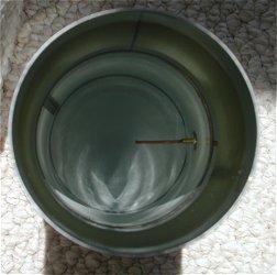
This is the first antenna I built. It's the ubiquitous circular waveguide
"cantenna":
I obtained my can by going to my local 99 Cents Only store and buying a can of
Heinz beans, which happened to be desired 3.25" diameter. The resultant methane
gas produced from consuming the beans was used to power my soldering iron
afterwards.
I will not go into the construction details, as they are very well documented
on Greg Rehm's
site. Finding his online cantenna calculator rather intriguing, I set out to
find the mathematical roots to his calculations. The result is my own cantenna
calculator program, which I wrote in in C++, based on formulae obtained from
the ARRL Antenna Book. It's available on my free
software page; the archive contains both a Win32 console-mode EXE and full
source code. In addition, Adam Lesser has kindly supplied a binary for
OS-X.
Greg Rehm's calculator fixes the operating frequency at Channel 6 (2437MHz),
which is the center channel in the USA, giving the best tradeoff if you want to
build a general purpose antenna which works across Channels 1-11. On the other
hand, my calculator lets you tune your antenna for maximum gain on a specific
channel; this is handy if you want to use your antenna set up a permanent point
to point link. Let's go through an example using my calculator. The syntax of
the program is
cantenna diameter centerchannel
where diameter is in mm. So to make an antenna optimized for Channel 6 using my
3.25" (82.55mm) diameter can, we would invoke it as follows:
So what's the meaning of all this gibberish? The probe should be 30.8mm
(1.21") long, and should be set 63mm (2.5") from the inside of the
back lid of the can. The operating wavelength of 4.8" shows us that
we don't have to worry that the sides of the can have ridges, because the their
depth is insignificant compared to the wavelength our signal. The Guide
Wavelength is the wavelength of our waveguide. The TE11/TM01 Cutoff frequencies
give us the approximate upper/lower frequencies of operation for our antenna.
Since Channel 1 is centered at 2412MHz and Channel 11 is centered at 2462 MHz,
we have a comfortable margin. Now the interesting part is that if you wanted to
tune the waveguide for the center frequency of Channel 1, you would use a probe
distance of 66.04mm instead, and for Channel 11, you would use 58.52mm. What
this means is that there is a whopping 5.48mm difference in the optimal probe
distance between Channels 1 and 11, so if you are going to use the antenna on a
fixed channel, it's better to enter than channel number instead when running the
program.
Experimenting with my calculator program, I've found some interesting
information. As the waveguide diameter increases, the difference in optimal
position for the driven element between Channels 1-11 drops. I tried
upping the diameter iteratively until the TM01 cutoff frequency started to go
too low to do Channel 11. From my studies, it seems that about 92mm is the
optimal diameter for the waveguide if you want to try to optimize it for
flattest response across Channels 1-11; this is because it minimizes the
difference in the probe position between Channels 1-11 -> about 2.63mm, so
the SWR curve across the WiFi band is flatter.
Contrary to popular belief on the Internet, a can length of 3/4 the waveguide
wavelength is not optimal. The ARRL Antenna book
recommends 2-3 waveguide wavelengths instead. I've found that adding more cans
indeed increases the gain. A 4-can one is the longest I tried; I didn't write
down the gain testing results, but it was considerably better than the 1-can
antenna. Adding more cans helps launch the standing waves in the can better. bmoore314
has some excellent info in this Netstumbler.com
thread, including info about adding a conical collector to it. My
results from experimenting with a conical collector are documented in the
section about my Bazooka Cantenna.
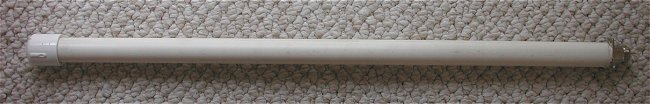
Toothpick Monopole
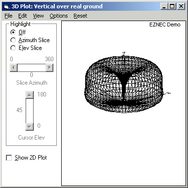
This is my first attempt at designing something myself. I downloaded the EZNEC
demo from www.eznec.com and started fiddling
with it. I still don't have a good grasp of how to model a real ground plane,
but i was able to get some plots and start tweaking things.
I started w/ a quarter wave whip. In the US, Channel 6 is the middle channel at
2.437GHz. This makes a quarter wavelength about 30.6mm, so I started with this
and just experimented w/ various lengths to change the pattern and SWR and ended
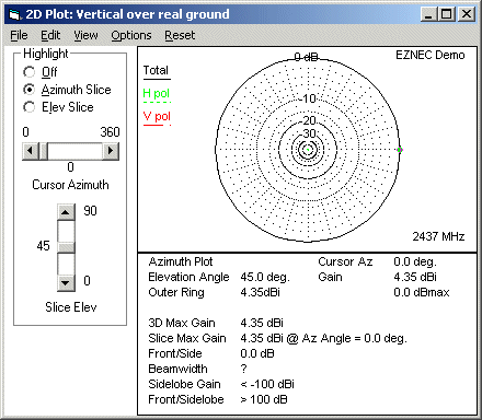
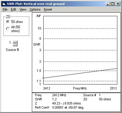
up with 89mm. EZNEC shows SWR of 1.2-1.6 over the WiFi band and gain of 4.35dB
max assuming a perfect ground (which we don't have). Below are plots of my EZNEC
model:
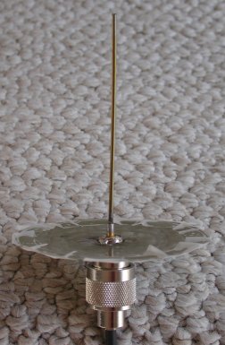
Here is my prototype:
It's just a piece of 2mm dia. coat hanger cut to 87mm and soldered into an
N-female panel jack for 89mm length from the tip to the base of the middle pin
on the jack. Just for the hell of it I soldered on the ground plane, which is
the lid of a 3.25" dia. tin can. The tape is just to keep me from shredding
my fingers on the sharp edges. How well does it work? I was amazed. walking
outside with MiniStumbler, i can find my AP 120ft farther away than with the
ORiNOCO built in antenna. Inside the house, I went the the place w/ the worst
reception and the signal & SNR went up by over 10dB vs the built in antenna.
I haven't even begun to tweak the thing yet. not bad for a $4 antenna (the cost
of the N jack).
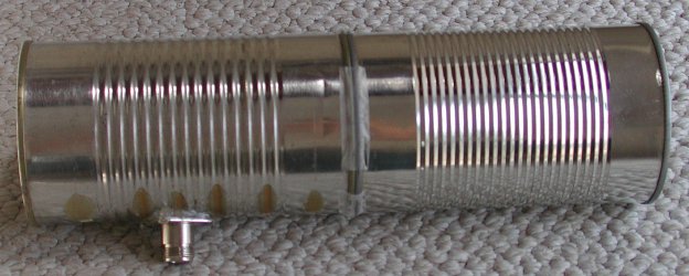
The Mobile Mark 5dBi
antenna is the stumbling antenna of choice used by many Netstumblers. outcast_one
was kind enough to post some pictures on the Netstumber.com website which were
clear enough to get measurements from. Hope he doesn't mind my re-posting them
here:
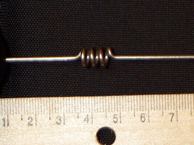
From the above photos, I estimated the dimensions below:
wire: ~1.5mm OD
ground plane to coils: 34mm (9.5mm of that is under the black plastic
bump..wonder what's in there?)
length of coils: 13mm
coil ID: 5mm
coil OD: 7mm
coil spacing: ~3-3.5mm
coils to top: 51.5mm+13mm(plastic tip)..wonder how high the wire goes into
the tip.
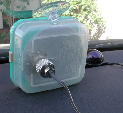
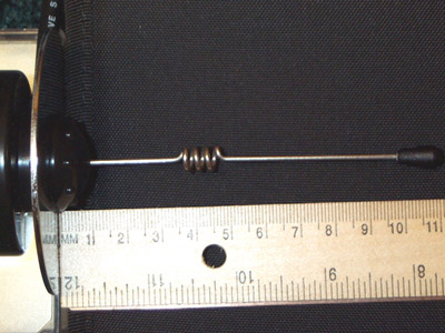
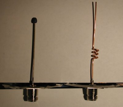
Here is my implemenation alongside my toothpick for comparison:
I used solid copper wire cut out of a piece of Romex...I forget the gauge..it
was all I had available; tried initially to bend a coat hanger but the steel
wire was too difficult to bend into the coils. Once again I used a 3.25"
can lid as the ground plane; this is close enough to Mobile Mark's specified
3" ground plane. A nicer implementation would be to use a discarded hard
disk platter (kudos to sparafina for that idea). I am worried that the
copper is too soft to stand up to high winds when attached to my car. When I get
a chance I will either encase the whole whip on a plastic tube or just support
the coil by inserting a suitable piece of plastic into it. Another idea is to
just fill the coil with hot glue.
My initial tests were not that promising...the gain was about the same as my
toothpick, except that the antenna seemed less sensitive to polarization.
However, stumbling with the antenna has shown that on the average, I pick up
AP's 1-2 car lengths farther away than with the toothpick, and the SNR is often
a little higher. Therefore, this antenna is used in my current stumbling rig.
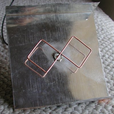
Trevor Marshall's BiQuad
Trevor Marshall has posted plans, as well as NEC2 models for his biquad
dish feed. The antenna can also be used standalone.
I fashioned the reflector from a discarded tin can. The reflector is 123x123mm,
with 30mm "lips" as specified by Trevor for standalone use. The driven
element is composed of copper wire I got out of a piece of Romex, with 30.5mm
legs, and is suspended 15mm above the reflector. The antenna as pictured above was
a complete failure and had horrible performance. Trevor explained to
me via e-mail that I messed up the feed (the photos on Trevor's site are
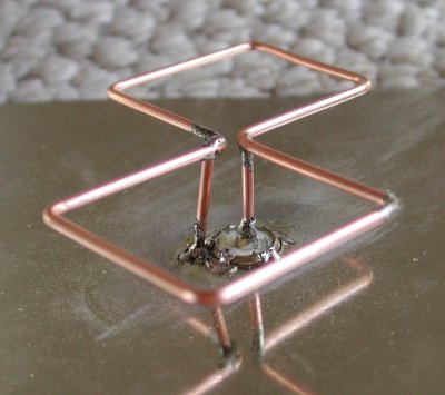
grainy). Here is my revised feed:
Instead of rigid coax as specified by Trevor, I just used some more copper wire
for the connections; I'm not sure how this affects VSWR, but the antenna gave me
about 3dB more gain than my Comtelco patch clone during my initial tests.
Bazooka Cantenna
I've been trying to hook up my brother, who is a professor at a local college to
his campus network. He lives just on the edge of campus, and although the IT
Dept. has discussed putting an AP on his side of the street, no progress has
been made for several months. Therefore, I decided to take matters into my own
hands. There are tons of AP's just around the corner and out of LOS from my
bro's house, but his block is strangely completely devoid of any signal.
Finally, one day I climbed up on his roof to see if I could get LOS and a signal
from a yagi on a hill which was pointed away from my brother's house. I used my
ORiNOCO card in my Jornada, pointed my biquad through a tree, and amazingly got
a 5dB SNR! Now we were in business, but the 5dB seemed a little too weak for
reliable communications, especially with the chance of the tree growing denser
foliage.
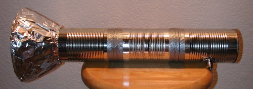
I decided a cantenna might be the way to go, so I built a new one using 3
3.25" diameter cans...this makes the total length about 1.75 waveguide
wavelengths. The driven element is 30.75mm long and mounted the 64mm from the
back of the can. The conical collector is 7.25" in diameter on the big
side, w/ a 30degree flare. This was just a quick prototype so I made the
collector out of 2 coat-hanger circles, separated w/ four 4" long coat
hanger supports covered in aluminum foil. the final design will need to be more
durable to stand up against wind & hail. Here is what it looks like:
Before trying it on the target site, I did some testing with my AP at home. Here
are the SNR's I got across the street from my AP:
ORiNOCO built in: 26 dB
2 cans w/o collector: 36 dB
3 cans w/o collector: 37-38 dB
Trevor Marshall biquad: 39 dB
3 cans w/ collector: 43 dB (!)
This is the highest gain antenna I've built yet. In my excitement, I dragged my
Jornada off a table while connected to this %$* thing and it fell on the floor.
Lucky the card & Jornada are ok, but I broke off the end of my pigtail.
The next morning, I climbed on my bro's roof armed w/ the bazooka cantenna.
Going back to the same place I got the 5dB SNR w/ the biquad, the bazooka got
8dB. I fired up PocketIE on the Jornada, and was able to surf a little -
paydirt! Since it was daylight this time, I was able to try out more places on
the roof, and finally found one clear of the tree which yielded 12dB SNR. Now
we're in business; I've got a little more margin to play with so when I hook up
the long LMR-400 cable to get the signal inside the house I won't get killed by
attenuation.
To be continued after I get the rest of the equipment to complete the
setup...
In the meantime, I played with the bazooka from the deck of my hillside house,
and was astonished to find that it picked up an AP I'd detected while stumbling
on the freeway in my car (using my Mobile Mark clone on the dash). Plugging the
GPS coordinates in from the freeway into Microsoft Streets & Trips, it turns
out the AP is about 4 miles away! Using the bazooka on at my house, the SNR was
8dB (signal ~-88dBm). As a comparison, I also tried the biquad. Using the
biquad, the signal is unstable w/ max 4dB SNR, and it catches the AP for only a
second at time.